
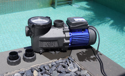


Yes—a variable-speed pool pump can run too slowly for the equipment connected to it. The pump may stay on and sound normal while a heater, salt-chlorine generator, cleaner, water feature, or even skimming performance falls below its usable flow condition. There is no universal minimum RPM for every pool. The useful target is the lowest verified setting for each operating mode, based on the strictest requirement among the devices active in that mode.
Separate the pump’s minimum from the system’s minimum
Three numbers are easy to confuse:
- Controller minimum RPM: The lowest speed the pump controller allows you to select.
- Pump operating point: The flow and head the pump actually produces in your plumbing at that speed.
- System minimum: The lowest flow that still satisfies every device active in a particular mode.
For the AQUASTRONG PSP150PM, PSP200PM, and PSP300PM, the shared instruction manual documents four adjustable speed presets between 1200 and 4000 RPM. It also lists a separate priming function that operates between 2900 and 4000 RPM.1 That means 1200 RPM is a selectable controller setting for those named pumps. It does not mean 1200 RPM will satisfy the heater, salt system, cleaner, water feature, or circulation needs of every installed pool.
Why RPM does not tell you GPM by itself
RPM describes shaft speed. GPM describes water flow. They are related, but they are not interchangeable. For the same centrifugal pump under comparable conditions, pump affinity relationships indicate that flow changes with speed, head changes roughly with the square of speed, and power changes roughly with the cube of speed. DOE also explains that the real operating point is where the pump curve meets the system curve.2 Your system curve changes with factors such as:
- Pipe diameter and length.
- Elbows, fittings, check valves, and other restrictions.
- Valve positions and which return branches are open.
- Filter condition.
- Water level and suction conditions.
- Heater, salt-cell, cleaner, solar, and water-feature paths.
- Equipment elevation relative to the pool.
Two pools using the same pump at the same RPM can therefore have different flow. Do not convert RPM to GPM using a chart from a different installation. If an equipment manual specifies a minimum GPM, use an appropriate installed flow meter or qualified commissioning method. A return jet that “looks strong enough” is not a flow measurement.
Build the equipment list before touching the schedule
Create one row for every device that shares the circulation path:
- Pump and filter.
- Heater or heat pump.
- Salt-chlorine generator or chemical controller.
- Suction-side, pressure-side, robotic, or in-floor cleaner.
- Waterfall, bubbler, deck jet, spa spillway, or other water feature.
- Solar-heating loop or another valved branch.
- Automation system that changes valves or calls equipment on.
For each item, record the exact model, manual link, required flow range or status condition, applicable valve position, and the warning or indicator that signals inadequate flow. Do not substitute a threshold from another model. As an example, Pentair states that its named IntelliChlor Plus & LT generators require 25 GPM (94.6 LPM) to activate the internal flow switch.3 A Jandy JXiQ manual specifies a 30 GPM minimum for the cited heater models.4 Those figures are not recommendations for your pool. They show why a salt system or heater can set a higher floor than the pump controller.
Start from a stable, safe baseline
Do not use an active fault or a poorly primed system to establish the minimum. Before testing:
- Confirm normal pool water level.
- Clean the pump basket and skimmer baskets using the documented shutdown procedure.
- Put the filter and valves in their normal operating positions.
- Confirm the pump is fully primed and that visible air clears normally.
- Check for leaks, damaged cords or wiring, repeated breaker or GFCI trips, burning odor, or abnormal heat.
- Start from a setting that already operates the system correctly.
- Keep swimmers out while you are changing and checking equipment modes.
CPSC identifies pumps and other powered pool equipment as potential shock sources in wet environments; water at electrical equipment is a stop condition, not a troubleshooting opportunity.5 The AQUASTRONG manual says never to run the pump dry or with the inlet blocked.1 Do not close a required flow path, open an electrical compartment, alter wiring, or reach into moving equipment. If the pump will not prime, air will not clear, or the system is already showing a flow fault, resolve that problem before lowering speed. Use the safe pump-start troubleshooting guide when the pump does not start normally.
Find the filtration-only setting first
Turn off optional dependent functions so the system is in its normal filtration-only configuration. Keep the filter and valves in the positions used for daily circulation. From the known working setting, reduce speed by one supported preset or small controller adjustment at a time. After each change, let the system stabilize for the period specified by the applicable manuals, then record:
- Selected RPM.
- Measured or indicated flow, if available.
- Filter pressure or other normal system indicator.
- Whether the pump remains fully primed.
- Whether persistent air appears in the pump basket or returns.
- Whether the skimmer weir and surface draw remain useful.
- Whether return flow remains stable.
- Any unusual rattling, gravel-like noise, surging, or fault code.
A moving skimmer weir or visible return flow is useful evidence, not proof that every connected device has enough flow. The filtration-only row establishes a circulation baseline; it does not automatically qualify the heater, salt cell, cleaner, or water feature.
Test one dependent function at a time
Return to the last known good setting before enabling the next device. Activate only one additional function, keep its normal valves in place, and repeat the controlled reduction.
Heater or heat-pump mode
Use the heater’s exact manual to identify minimum flow, required valve configuration, and flow- or pressure-related alarms. Stop lowering speed when:
- The measured flow approaches the documented minimum.
- A low-flow or pressure warning appears.
- The heater cycles off unexpectedly.
- The pump loses prime, surges, or develops abnormal noise.
Do not repeatedly force a heater into a fault to identify the threshold, and never adjust or bypass its pressure or flow switch. If the heater requires a GPM value you cannot verify, ask a qualified pool professional to commission that mode.
Salt-chlorination mode
Confirm the cell’s flow indicator remains in its normal operating state at the tested setting. Then confirm chlorine output using the normal water-testing routine over time; the flow indicator alone does not prove the pool’s sanitizer demand is being met. If a low-flow indicator appears, return to the last passing setting. Do not bypass the flow switch or assume another brand’s minimum GPM applies.
Cleaner mode
Identify the cleaner type first. A robotic cleaner may be hydraulically independent, while suction-side, pressure-side, and in-floor systems can depend on circulation flow, valve position, or a separate booster pump. Use the cleaner manual’s movement, pressure, flow, and valve criteria. “It moves sometimes” is not a reliable pass condition if the manual expects a specific gauge or flow indicator.
Water-feature or spa-spillway mode
Appearance is part of the requirement: a waterfall that breaks into uneven streams or a spillway that cannot maintain the intended sheet may need a higher setting than filtration alone. Use only the normal automation and valve positions. Do not throttle or close a path outside the documented configuration simply to make one feature appear stronger.
Let the strictest active requirement set each mode
Do not search for one lowest number for the entire pool. Create a schedule with separate modes.
| Operating mode | Active equipment | Passing evidence | Stop-lowering signal | Retained setting |
|---|---|---|---|---|
| Filtration only | Pump, filter, skimmer, returns | Stable prime; useful surface draw and return flow; normal indicators | Persistent air, surging, poor skimming, abnormal noise, or fault | Lowest verified passing setting plus a documented margin |
| Heating | Filtration equipment plus heater or heat pump | Documented minimum flow met; stable operation; no flow/pressure alarm | Approaching manual minimum, cycling, alarm, or unstable flow | Higher of filtration or heater requirement, plus margin |
| Salt chlorination | Filtration equipment plus salt cell | Normal flow status and documented minimum met | Low-flow indication or unverified GPM requirement | Higher of filtration or salt-system requirement, plus margin |
| Cleaner | Filtration path plus hydraulic cleaner or booster system | Manual-specified movement, pressure, or flow condition | Stalling, intermittent action, bad gauge reading, or fault | Lowest verified cleaner-mode setting plus margin |
| Water feature or spa spillway | Filtration path plus feature branch | Stable pump operation and intended visual output | Broken output, air, unstable flow, or equipment warning | Lowest verified feature-mode setting plus margin |
For each row, the controlling requirement is the highest verified minimum among the devices active in that mode. The retained setting should remain above the lowest passing point. There is no universal safety margin. Normal filter loading, debris in baskets, valve changes, water-level changes, and small air leaks can increase system resistance, so preserve only a margin supported by the manuals or a qualified commissioning result.
Save the worksheet, not just the RPM
A defensible record makes future troubleshooting much easier. Use this worksheet:
| Date and mode | Equipment and valve position | Manual requirement | Test RPM | Measured/indicated flow | Observed status | Final preset |
|---|---|---|---|---|---|---|
| Example: filtration only | Record exact filter and normal circulation path | Enter verified requirement or “not specified” | Record selected setting | Record flow-meter or equipment display value, if available | Prime, air, pressure, skimming, returns, noise, and faults | Record the retained setting and reason |
Repeat the worksheet after:
- A filter or pump replacement.
- Plumbing or valve changes.
- Adding a heater, salt cell, cleaner, or water feature.
- Automation changes.
- A recurring low-flow or pressure alarm.
- A material change in normal filter condition or circulation behavior.
This is different from choosing daily runtime. Once the operating modes are verified, use the conditions-based pool-pump schedule guide to decide how long each mode should run. If you are still selecting equipment, read the variable-speed versus single-speed comparison and the pool-pump sizing worksheet. Sizing, speed, and runtime answer different questions.
Stop the test when the risk rises
Stop changing settings and arrange qualified service when you see:
- Loss of prime or dry-running risk.
- Persistent air that does not clear.
- A leak that reaches electrical equipment.
- Damaged wiring, arcing, smoke, or burning odor.
- Repeated breaker or GFCI trips.
- A hot control enclosure or cord.
- Strong vibration, grinding, or gravel-like noise.
- A heater, salt system, or automation flow fault that does not clear at a previously verified setting.
- A required GPM value that cannot be measured or confirmed.
- Any need to open electrical, heater, salt-cell, pump-drive, or internal plumbing components.
For AQUASTRONG equipment, begin with the product-manual library. Keep the model numbers, completed worksheet, photos of valve positions, and fault codes ready for AQUASTRONG support or a qualified pool professional.

About the author